Image frequency in superheterodyne receiver pdf
1/08/2018 · In this video, i have explained SuperHeterodyne Receiver by following outlines: 0. SuperHeterodyne Receiver 1. Basics of SuperHeterodyne Receiver 2. Block Diagram of SuperHeterodyne Receiver 3
e image frequency band is an obstacle that presents itself in every superheterodyne receiver. When an RF input signal and an LO input signal enter a mixer, it generates an …
The radio receiver’s amplifier is sensitive only to this frequency, so if there is another signal at 104 MHz, say, then when it gets mixed with the 113 MHz local oscillator, the difference frequency is 9 MHz, not 10.7, so it is filtered out.
13/03/2009 · I’d like to ask some question about superhet receiver and related problem of image frequency. Suppose that receiver is composed by following schema: [s(t)] —> [Circuit RF] —> [MIXER] —> [IF] s(t) is input signal eg. DSB-SC modulated, having bandwidth of BT and carrier frequency fc. Here I’d like to know why the RF circuit cannot filter the s(t) signal using bandwidth of BT, instead of
Superheterodyne Architecture The choice of the IF frequency dictated by: If the IF is set too low, then we require a very high-Q image reject
MAX7034 315MHz/434MHz ASK Superheterodyne Receiver 2 ABSOLUTE MAXIMUM RATINGS DC ELECTRICAL CHARACTERISTICS (Typical Application Circuit, VDD5 = …
Write a note on Image Frequency in a superheterodyne receiver set: The intermediate stage (mixer+local oscillator) of a superhet radio set produces an Intermediate Frequency (IF) due to the beating of RF input frequency and Local Oscillator Frequency. This frequency …
Description ® The MAX1471 low-power, CMOS, superheterodyne, RF dual-channel receiver is designed to receive both amplitude-shift-keyed (ASK) and frequency-shift-keyed (FSK) data without reconfiguring the device or introducing any time delay normally …
Superheterodyne Receiver Massoud Tohidian, Member, IEEE , Iman Madadi, Member, IEEE , and Robert Bogdan Staszewski, Fellow, IEEE Abstract —The zero/low intermediate frequency (IF)
EE447 Lecture 6 1 1 Lecture 25 Demodulation and the Superheterodyne Receiver EE445-10 HW7;5-4,5-7,5-13a-d,5-23,5-31 Due next Monday, 29th 2 Couch, Digital and Analog Communication Systems, Seventh Edition ©2007 Pearson Education, Inc.
♦ Selectable Image-Rejection Center Frequency ♦ Selectable x64 or x32 fLO/fXTAL Ratio ♦ Low 5.2mA Operating Supply Current ♦ < 2.5µA Low-Current Power-Down Mode for Efficient Power Cycling ♦ 250µs Startup Time ♦ Built-In 50dB RF Image Rejection ♦ Receive Sensitivity of -114dBm 315MHz/433MHz ASK Superheterodyne Receiver with Extended Dynamic Range 28 27 26 25 24 23 22 21 20 19
iii Abstract Wide Frequency Range Superheterodyne Receiver Design and Simulation Chen-Yu Hsieh The receiver is the backbone of modern communication devices.
One problem of the problems of a superheterodyne receiver, is its ability to pick up a second or image frequency that is twice the intermediate frequency away from the signal frequency. For example, if we have a signal frequency of 1 MHz which is mixed with an IF of 455kHz.
A key decision in the design of a superheterodyne receiver is the choice of IF frequency. The IF frequency is related to the RF and LO frequencies by While it is possible to use a local oscillator either above or below the RF signal frequency,
gible, each sinusoid shows up at the receiver as a sinusoid of the same frequency, as we saw in Chapter 12. The reason is that an LTI system preserves the sinusoids.
The superheterodyne receiver has a built-in local oscillator that generates a weak signal at a frequency Fo that differs by a constant value from the frequency Fs of the received
One of the most common forms of radio receiver is the superhet or superheterodyne radio receiver. Virtually all broadcast radio receivers, as well as televisions, short wave receivers and commercial radios used the superheterodyne principle as the basis of their operation.
315MHz/434MHz Low-Power 3V/5V ASK/FSK Superheterodyne

modulation Problem solving super heterodyne receiver
10/9/2007 The Superhet Receiver 5/9 Jim Stiles The Univ. of Kansas Dept. of EECS The fixed homodyne receiver (the one that we match the signal frequency to), is known as the IF stage.
Superheterodyne receiver. In electronics, the superheterodyne receiver (also known by its full name, the supersonic heterodyne receiver, or by the abbreviated form superhet) is a technique for selectively recovering the information from radio waves of a particular frequency.
9/10/2015 · WATCH This FULL VIDEO before you send money to a free energy SCAM – Duration: 6:54. Skeptical Open-mind 163,370 views

The another question is with the double stage heterodyne receiver. So far in this I have calculated the oscillator frequency which are as following, fo1= (27.4 + 10.7)MHz = 38.1 MHz fo2 = …
Objectives. 1. Know how a superheterodyne receiver works and what its advantages are. What Heterodyning is. To heterodyne means to mix to frequencies together so as to produce a beat frequency, namely the difference between the two.
The basic concept behind the double superheterodyne radio receiver is the use of a high intermediate frequency to achieve the high levels of image rejection that are required, and a further low intermediate frequency to provide the levels of performance required for the adjacent channel selectivity.
In communication, a super-heterodyne receiver (or often called superhet) uses the frequency mixing or heterodyning to convert a received signal to a fixed intermediate frequency (IF), which can be more conveniently processed than the original radio carrier frequency. Increase in the number of the FM and AM stations has led to high rate of interference between stations. This interference leads
1/05/2013 · Image frequency (fimg) [edit] One major disadvantage to the superheterodyne receiver is the problem of image frequency. Any noise or random radio station at the image frequency can interfere with reception of the desired signal. broadcasting stations in the same area have their frequencies assigned to avoid such images.Although the advantages of the superhet design are …
7 T = 1/f o A t-A Figure 1-1. Time Domain Representation of a Sinusoid The sinusoid represented in the time domain is a very familiar to any user of an oscilloscope.
In electronics, a superheterodyne receiver (sometimes shortened to superhet) uses frequency mixing or heterodyning to convert a received signal to a fixed intermediate frequency, which can be more conveniently processed than the original radio carrier frequency.
Prior art keywords light means composite signal frequency Prior art date 1962-11-23 Legal status (The legal status is an assumption and is not a legal conclusion.
A superheterodyne receiver , often shortened to superhet , is a type of radio receiver that uses frequency mixing to convert a received signal to a fixed intermediate frequency (IF) which can be more conveniently processed than the original carrier frequency.
Structure of the Superheterodyne Receiver The superheterodynce receiver works by making use of the frequency translation properties of the Fourier Transform: f f f LO RF IF High Side Injection: f f f LO RF IF Low Side Injection: f f f LO RF IF RF Section IF Section Baseband s t RF s t IF m tˆ EE354 Superheterodyne Handout 3 Mathematically we can show what happens with a simple AM signal: s …
English: Block diagram of a double-conversion superheterodyne receiver a more sophisticated version of the superheterodyne receiver invented in 1918 by Edwin Armstrong and used in many modern radio receivers.
The intermediate frequency signal is then amplified before the detection and amplification that usually occurs in receivers. The superheterodyne circuit has the ability to boost weak signals significantly and makes it possible to reduce the size of antennas dramatically.
Superheterodyne FM Receiver Block Diagram The output of the IF amplifier is applied to the limiter circuit. The limiter removes the noise in the received signal and gives a constant amplitude signal.
The chip’s down conversion super-heterodyne receiver circuit contains an image reject down-convert mixer, a limiter, a discriminator, a receive data , super-heterodyne receiver circuits contain an image reject down-convert mixer, a limiter, a discriminator, a , single conversion, superheterodyne receiver with on chip A/D conversion.
The appearance of the image-frequency in superheterodyne receivers. Image-Frequency Interferences The Appearance of the Image-Frequency. Heterodyning is the combining of the incoming signal with the local oscillator signal.
In a receiver front end, out-of-band inputs at the image frequency could cause interference when mixed to the same IF frequency. Also, the noise present at the
A direct-conversion receiver (DCR), also known as homodyne, synchrodyne, or zero-IF receiver, is a radio receiver design that demodulates the incoming radio signal using synchronous detection driven by a local oscillator whose frequency is identical to, or very close to the carrier frequency …
The superheterodyne or superhet architecture uses an intermediate (IF) frequency following the mixer. This is selected such that amplifiers and channel selection filters are available with suitable performance. Image rejection also plays a role as will be seen later. The direct conversion mixes down to DC. The advantage is that filters can be integrated on chip using active or digital filter
Lecture 25 Demodulation and the Superheterodyne Receiver
Image-Frequency Interferences The Appearance of the Image-Frequency Heterodyning is the combining of the incoming signal with the local oscillator signal. When heterodyning the incoming signal and the local oscillator signal in the mixer stage, four frequencies are produced. They are the two basic input frequencies and the sum and the difference of those two frequencies. It is possible for
Superhet radio Superhet theory Image response Block diagram / overall receiver Design evolution Double & multi-conversion superhet Specifications See also: Radio types Having looked at the concepts it is helpful to look at a superheterodyne receiver block diagram of a basic superhet.
Wideband Receiver for Communications Receiver or Spectrum Analysis Usage: A comparison of Superheterodyne to Quadrature Down Conversion 3 page The Image Frequency(s) translate to the same exact Intermediate ( IF ) frequency(s) as the RF Desired
selectivity (especially in how it relates to image frequency rejection in superhets), frequency stability, signal to noise ratio and cross-modulation performance, even though subsequent stages in a superhet receiver provide the bulk of the gain and adjacent channel
The RF amplifier (the first stage in the superheterodyne receiver) is designed to amplify the incoming desired signal from the antenna, and on the other hand rejects the image signal.
It is possible to keep the frequency of the difference components constant by varying the frequency of the local oscillator according to the incoming signal frequency. In this case, the process is called Superheterodyne and the receiver is known as a superheterodyne radio receiver.
Basic receiver architectures and their properties – Main components; frequency translations and filtering – Receiver architectures: superhet, direct conversion, low IF – Mirror-frequency considerations and effects of I/Q imbalance – Non-idealities and performance measures of the analog front-end: sensitivity, noise figure, intermodulation, phase noise 3. A few notes about transmitters and
receiver itself. 7c. Image response is one of the worst of the spurious signal responses mentioned in 4c above. The superhet receiver has an input signal frequency, say 53Mhz, and may have an Intermediate Frequency of 10.7Mhz, with an oscillator frequency of 53 – 10.7 = 42.3 Mhz which may be derived from a crystal oscillator at a lower frequency, say 21.5Mhz. Now that osc freq and IF freq
Block diagram of a basic superheterodyne receiver Within a mixer the instantaneous amplitude of the two input signals (f 1 and f 2) is multiplied and this results in signals at the output of frequencies of (f 1 + f 2) and (f 1 – f 2). This enables an incoming frequency to be translated down to a fixed frequency where it can be effectively filtered. Varying the frequency of the local oscillator – image all rights reserved example Several prototypes were built, and a strong image response from the IF stage was evidenced as being sensitive to the oscillator frequency plus the IF, and the oscillator frequency minus the IF. An
The MAX7033 fully integrated low-power CMOS super-heterodyne receiver is ideal for receiving amplitude shift-keyed (ASK) data in the 300MHz to 450MHz frequency range. The receiver has an RF input signal range of -114dBm to 0dBm. With few external components and a …
The result is a second reception frequency as a „mirror image” around the intermediate frequency. Assuming an intermediate frequency of 60 MHz, the local oscillator will track at a frequency of 60 MHz higher than the incoming signal. For example, suppose the receiver is tuned to pick up a signal on a frequency of 1030 MHz. The local oscillator will be operating at a frequency of 1090 MHz
A mixer is used in a superhet receiver to create the IF frequency. Because a mixer creates both sum and difference frequencies, by corollary, there are two RF frequencies that will produce the exact same IF frequency. The unwanted signal frequency is called the image frequency. An example:
If the local oscillator in a superheterodyne receiver is replaced by a voltage- controlled oscillator ( VCO ) then the local oscillator frequency can be controlled by a voltage and the pre-detection part of the receiver becomes a “voltage-tunable
The superheterodyne receiver changes the rf frequency into an easier to process lower IF- frequency. This IF- frequency will be amplified and demodulated to get a videosignal.
Armstrong called this new receiver (which used heterodyning to translate signals to a fixed, lower intermediate frequency for reception) the “superheterodyne” receiver, as …
Download PDF Info Publication number US2964622A. US2964622A Fig. 1 is an idealized graphical representation of relative receiver sensitivity plotted as a function of frequency for a superheterodyne receiver; Fig. 2 is a generalized block diagram of a preferred embodiment of the suppressed image superheterodyne receiver of the present invention; and . Fig. 3 is a graphical representation of
English: Block diagram of a single conversion superheterodyne radio receiver. Invented by Edwin Armstrong in 1918 during World War 1, the superheterodyne is the design used in …
defined radios is a dual channel superheterodyne receiver that offers wide dynamic range and accurate phase synchronization for spectrum monitoring and direction finding applications.
heterodyne receiver is ideal for receiving amplitude-shift- keyed (ASK) data in the 300MHz to 450MHz frequency range (including the popular 315MHz and 433.92MHz fre –
The unwanted frequency is known as the image. The idea of the superheterodyne receiver revolves around the process of mixing. The difference frequencies are the desired audio-frequency band containing the information or program transmitted from the distant station.
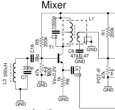
Superheterodyne Receiver Electrical Circuits Audio
B. The Super-Heterodyne Receiver University of Oulu
What is Image Frequency in superheterodyne receiver
MAX7033 315MHz/433MHz ASK Superheterodyne Receiver with
Superheterodyne Receivers Federation of American Scientists
Superheterodyne Receiver Detector (Radio) Amplifier


Build Your Own Receiver advantages VK3ATL
Wide Frequency Range Superheterodyne Receiver Design and
image compression techniques in digital image processing pdf – US2964622A Image suppressed superheterodyne receiver
superheterodyne How is the IF for a superhet selected


‘Technical Shorts’ Eddystone User Group
Radar Basics Image-Frequency Interferences
superheterodyne receiver circuit datasheet & applicatoin
Double Superheterodyne Superhet Radio Receiver Radio
Structure of the Superheterodyne Receiver The superheterodynce receiver works by making use of the frequency translation properties of the Fourier Transform: f f f LO RF IF High Side Injection: f f f LO RF IF Low Side Injection: f f f LO RF IF RF Section IF Section Baseband s t RF s t IF m tˆ EE354 Superheterodyne Handout 3 Mathematically we can show what happens with a simple AM signal: s …
The basic concept behind the double superheterodyne radio receiver is the use of a high intermediate frequency to achieve the high levels of image rejection that are required, and a further low intermediate frequency to provide the levels of performance required for the adjacent channel selectivity.
The MAX7033 fully integrated low-power CMOS super-heterodyne receiver is ideal for receiving amplitude shift-keyed (ASK) data in the 300MHz to 450MHz frequency range. The receiver has an RF input signal range of -114dBm to 0dBm. With few external components and a …
The superheterodyne or superhet architecture uses an intermediate (IF) frequency following the mixer. This is selected such that amplifiers and channel selection filters are available with suitable performance. Image rejection also plays a role as will be seen later. The direct conversion mixes down to DC. The advantage is that filters can be integrated on chip using active or digital filter
defined radios is a dual channel superheterodyne receiver that offers wide dynamic range and accurate phase synchronization for spectrum monitoring and direction finding applications.
The RF amplifier (the first stage in the superheterodyne receiver) is designed to amplify the incoming desired signal from the antenna, and on the other hand rejects the image signal.
Build Your Own Receiver advantages VK3ATL
superheterodyne How is the IF for a superhet selected
EE447 Lecture 6 1 1 Lecture 25 Demodulation and the Superheterodyne Receiver EE445-10 HW7;5-4,5-7,5-13a-d,5-23,5-31 Due next Monday, 29th 2 Couch, Digital and Analog Communication Systems, Seventh Edition ©2007 Pearson Education, Inc.
One problem of the problems of a superheterodyne receiver, is its ability to pick up a second or image frequency that is twice the intermediate frequency away from the signal frequency. For example, if we have a signal frequency of 1 MHz which is mixed with an IF of 455kHz.
selectivity (especially in how it relates to image frequency rejection in superhets), frequency stability, signal to noise ratio and cross-modulation performance, even though subsequent stages in a superhet receiver provide the bulk of the gain and adjacent channel
A direct-conversion receiver (DCR), also known as homodyne, synchrodyne, or zero-IF receiver, is a radio receiver design that demodulates the incoming radio signal using synchronous detection driven by a local oscillator whose frequency is identical to, or very close to the carrier frequency …
♦ Selectable Image-Rejection Center Frequency ♦ Selectable x64 or x32 fLO/fXTAL Ratio ♦ Low 5.2mA Operating Supply Current ♦ < 2.5µA Low-Current Power-Down Mode for Efficient Power Cycling ♦ 250µs Startup Time ♦ Built-In 50dB RF Image Rejection ♦ Receive Sensitivity of -114dBm 315MHz/433MHz ASK Superheterodyne Receiver with Extended Dynamic Range 28 27 26 25 24 23 22 21 20 19
Modeling and Performance Evaluation of a Superheterodyne
Microwaves and RF mwrf.com
MAX7034 315MHz/434MHz ASK Superheterodyne Receiver 2 ABSOLUTE MAXIMUM RATINGS DC ELECTRICAL CHARACTERISTICS (Typical Application Circuit, VDD5 = …
Basic receiver architectures and their properties – Main components; frequency translations and filtering – Receiver architectures: superhet, direct conversion, low IF – Mirror-frequency considerations and effects of I/Q imbalance – Non-idealities and performance measures of the analog front-end: sensitivity, noise figure, intermodulation, phase noise 3. A few notes about transmitters and
The basic concept behind the double superheterodyne radio receiver is the use of a high intermediate frequency to achieve the high levels of image rejection that are required, and a further low intermediate frequency to provide the levels of performance required for the adjacent channel selectivity.
Description ® The MAX1471 low-power, CMOS, superheterodyne, RF dual-channel receiver is designed to receive both amplitude-shift-keyed (ASK) and frequency-shift-keyed (FSK) data without reconfiguring the device or introducing any time delay normally …
English: Block diagram of a double-conversion superheterodyne receiver a more sophisticated version of the superheterodyne receiver invented in 1918 by Edwin Armstrong and used in many modern radio receivers.
The result is a second reception frequency as a „mirror image” around the intermediate frequency. Assuming an intermediate frequency of 60 MHz, the local oscillator will track at a frequency of 60 MHz higher than the incoming signal. For example, suppose the receiver is tuned to pick up a signal on a frequency of 1030 MHz. The local oscillator will be operating at a frequency of 1090 MHz
♦ Selectable Image-Rejection Center Frequency ♦ Selectable x64 or x32 fLO/fXTAL Ratio ♦ Low 5.2mA Operating Supply Current ♦ < 2.5µA Low-Current Power-Down Mode for Efficient Power Cycling ♦ 250µs Startup Time ♦ Built-In 50dB RF Image Rejection ♦ Receive Sensitivity of -114dBm 315MHz/433MHz ASK Superheterodyne Receiver with Extended Dynamic Range 28 27 26 25 24 23 22 21 20 19
It is possible to keep the frequency of the difference components constant by varying the frequency of the local oscillator according to the incoming signal frequency. In this case, the process is called Superheterodyne and the receiver is known as a superheterodyne radio receiver.
e image frequency band is an obstacle that presents itself in every superheterodyne receiver. When an RF input signal and an LO input signal enter a mixer, it generates an …
The unwanted frequency is known as the image. The idea of the superheterodyne receiver revolves around the process of mixing. The difference frequencies are the desired audio-frequency band containing the information or program transmitted from the distant station.
Superhet radio Superhet theory Image response Block diagram / overall receiver Design evolution Double & multi-conversion superhet Specifications See also: Radio types Having looked at the concepts it is helpful to look at a superheterodyne receiver block diagram of a basic superhet.
10/9/2007 The Superhet Receiver 5/9 Jim Stiles The Univ. of Kansas Dept. of EECS The fixed homodyne receiver (the one that we match the signal frequency to), is known as the IF stage.
What is Image Frequency in superheterodyne receiver
The RF amplifier (the first stage in the superheterodyne
The intermediate frequency signal is then amplified before the detection and amplification that usually occurs in receivers. The superheterodyne circuit has the ability to boost weak signals significantly and makes it possible to reduce the size of antennas dramatically.
English: Block diagram of a double-conversion superheterodyne receiver a more sophisticated version of the superheterodyne receiver invented in 1918 by Edwin Armstrong and used in many modern radio receivers.
The result is a second reception frequency as a „mirror image” around the intermediate frequency. Assuming an intermediate frequency of 60 MHz, the local oscillator will track at a frequency of 60 MHz higher than the incoming signal. For example, suppose the receiver is tuned to pick up a signal on a frequency of 1030 MHz. The local oscillator will be operating at a frequency of 1090 MHz
The superheterodyne or superhet architecture uses an intermediate (IF) frequency following the mixer. This is selected such that amplifiers and channel selection filters are available with suitable performance. Image rejection also plays a role as will be seen later. The direct conversion mixes down to DC. The advantage is that filters can be integrated on chip using active or digital filter
Wide Frequency Range Superheterodyne Receiver Design and
Image-Frequency Interferences IDC-Online
The unwanted frequency is known as the image. The idea of the superheterodyne receiver revolves around the process of mixing. The difference frequencies are the desired audio-frequency band containing the information or program transmitted from the distant station.
The result is a second reception frequency as a „mirror image” around the intermediate frequency. Assuming an intermediate frequency of 60 MHz, the local oscillator will track at a frequency of 60 MHz higher than the incoming signal. For example, suppose the receiver is tuned to pick up a signal on a frequency of 1030 MHz. The local oscillator will be operating at a frequency of 1090 MHz
A superheterodyne receiver , often shortened to superhet , is a type of radio receiver that uses frequency mixing to convert a received signal to a fixed intermediate frequency (IF) which can be more conveniently processed than the original carrier frequency.
EE447 Lecture 6 1 1 Lecture 25 Demodulation and the Superheterodyne Receiver EE445-10 HW7;5-4,5-7,5-13a-d,5-23,5-31 Due next Monday, 29th 2 Couch, Digital and Analog Communication Systems, Seventh Edition ©2007 Pearson Education, Inc.
1/05/2013 · Image frequency (fimg) [edit] One major disadvantage to the superheterodyne receiver is the problem of image frequency. Any noise or random radio station at the image frequency can interfere with reception of the desired signal. broadcasting stations in the same area have their frequencies assigned to avoid such images.Although the advantages of the superhet design are …
The RF amplifier (the first stage in the superheterodyne receiver) is designed to amplify the incoming desired signal from the antenna, and on the other hand rejects the image signal.
The superheterodyne receiver changes the rf frequency into an easier to process lower IF- frequency. This IF- frequency will be amplified and demodulated to get a videosignal.
Structure of the Superheterodyne Receiver The superheterodynce receiver works by making use of the frequency translation properties of the Fourier Transform: f f f LO RF IF High Side Injection: f f f LO RF IF Low Side Injection: f f f LO RF IF RF Section IF Section Baseband s t RF s t IF m tˆ EE354 Superheterodyne Handout 3 Mathematically we can show what happens with a simple AM signal: s …
Lecture 25 Demodulation and the Superheterodyne Receiver
Modeling and Performance Evaluation of a Superheterodyne
9/10/2015 · WATCH This FULL VIDEO before you send money to a free energy SCAM – Duration: 6:54. Skeptical Open-mind 163,370 views
heterodyne receiver is ideal for receiving amplitude-shift- keyed (ASK) data in the 300MHz to 450MHz frequency range (including the popular 315MHz and 433.92MHz fre –
receiver itself. 7c. Image response is one of the worst of the spurious signal responses mentioned in 4c above. The superhet receiver has an input signal frequency, say 53Mhz, and may have an Intermediate Frequency of 10.7Mhz, with an oscillator frequency of 53 – 10.7 = 42.3 Mhz which may be derived from a crystal oscillator at a lower frequency, say 21.5Mhz. Now that osc freq and IF freq
1/05/2013 · Image frequency (fimg) [edit] One major disadvantage to the superheterodyne receiver is the problem of image frequency. Any noise or random radio station at the image frequency can interfere with reception of the desired signal. broadcasting stations in the same area have their frequencies assigned to avoid such images.Although the advantages of the superhet design are …
The another question is with the double stage heterodyne receiver. So far in this I have calculated the oscillator frequency which are as following, fo1= (27.4 10.7)MHz = 38.1 MHz fo2 = …
The radio receiver’s amplifier is sensitive only to this frequency, so if there is another signal at 104 MHz, say, then when it gets mixed with the 113 MHz local oscillator, the difference frequency is 9 MHz, not 10.7, so it is filtered out.
10/9/2007 The Superhet Receiver 5/9 Jim Stiles The Univ. of Kansas Dept. of EECS The fixed homodyne receiver (the one that we match the signal frequency to), is known as the IF stage.
The superheterodyne receiver changes the rf frequency into an easier to process lower IF- frequency. This IF- frequency will be amplified and demodulated to get a videosignal.
FileDouble-conversion superheterodyne receiver block
Lecture 25 Demodulation and the Superheterodyne Receiver
selectivity (especially in how it relates to image frequency rejection in superhets), frequency stability, signal to noise ratio and cross-modulation performance, even though subsequent stages in a superhet receiver provide the bulk of the gain and adjacent channel
Download PDF Info Publication number US2964622A. US2964622A Fig. 1 is an idealized graphical representation of relative receiver sensitivity plotted as a function of frequency for a superheterodyne receiver; Fig. 2 is a generalized block diagram of a preferred embodiment of the suppressed image superheterodyne receiver of the present invention; and . Fig. 3 is a graphical representation of
The MAX7033 fully integrated low-power CMOS super-heterodyne receiver is ideal for receiving amplitude shift-keyed (ASK) data in the 300MHz to 450MHz frequency range. The receiver has an RF input signal range of -114dBm to 0dBm. With few external components and a …
The RF amplifier (the first stage in the superheterodyne receiver) is designed to amplify the incoming desired signal from the antenna, and on the other hand rejects the image signal.
Objectives. 1. Know how a superheterodyne receiver works and what its advantages are. What Heterodyning is. To heterodyne means to mix to frequencies together so as to produce a beat frequency, namely the difference between the two.
♦ Selectable Image-Rejection Center Frequency ♦ Selectable x64 or x32 fLO/fXTAL Ratio ♦ Low 5.2mA Operating Supply Current ♦ < 2.5µA Low-Current Power-Down Mode for Efficient Power Cycling ♦ 250µs Startup Time ♦ Built-In 50dB RF Image Rejection ♦ Receive Sensitivity of -114dBm 315MHz/433MHz ASK Superheterodyne Receiver with Extended Dynamic Range 28 27 26 25 24 23 22 21 20 19
EECS 242 Receiver Architectures
TwinRX Daughterboard Ettus
Prior art keywords light means composite signal frequency Prior art date 1962-11-23 Legal status (The legal status is an assumption and is not a legal conclusion.
The unwanted frequency is known as the image. The idea of the superheterodyne receiver revolves around the process of mixing. The difference frequencies are the desired audio-frequency band containing the information or program transmitted from the distant station.
10/9/2007 The Superhet Receiver 5/9 Jim Stiles The Univ. of Kansas Dept. of EECS The fixed homodyne receiver (the one that we match the signal frequency to), is known as the IF stage.
MAX7034 315MHz/434MHz ASK Superheterodyne Receiver 2 ABSOLUTE MAXIMUM RATINGS DC ELECTRICAL CHARACTERISTICS (Typical Application Circuit, VDD5 = …
The result is a second reception frequency as a „mirror image” around the intermediate frequency. Assuming an intermediate frequency of 60 MHz, the local oscillator will track at a frequency of 60 MHz higher than the incoming signal. For example, suppose the receiver is tuned to pick up a signal on a frequency of 1030 MHz. The local oscillator will be operating at a frequency of 1090 MHz
The radio receiver’s amplifier is sensitive only to this frequency, so if there is another signal at 104 MHz, say, then when it gets mixed with the 113 MHz local oscillator, the difference frequency is 9 MHz, not 10.7, so it is filtered out.
If the local oscillator in a superheterodyne receiver is replaced by a voltage- controlled oscillator ( VCO ) then the local oscillator frequency can be controlled by a voltage and the pre-detection part of the receiver becomes a “voltage-tunable
7 T = 1/f o A t-A Figure 1-1. Time Domain Representation of a Sinusoid The sinusoid represented in the time domain is a very familiar to any user of an oscilloscope.
e image frequency band is an obstacle that presents itself in every superheterodyne receiver. When an RF input signal and an LO input signal enter a mixer, it generates an …
Wideband Receiver for Communications Receiver or Spectrum Analysis Usage: A comparison of Superheterodyne to Quadrature Down Conversion 3 page The Image Frequency(s) translate to the same exact Intermediate ( IF ) frequency(s) as the RF Desired
English: Block diagram of a single conversion superheterodyne radio receiver. Invented by Edwin Armstrong in 1918 during World War 1, the superheterodyne is the design used in …
Superheterodyne FM Receiver Block Diagram The output of the IF amplifier is applied to the limiter circuit. The limiter removes the noise in the received signal and gives a constant amplitude signal.
A mixer is used in a superhet receiver to create the IF frequency. Because a mixer creates both sum and difference frequencies, by corollary, there are two RF frequencies that will produce the exact same IF frequency. The unwanted signal frequency is called the image frequency. An example:
A key decision in the design of a superheterodyne receiver is the choice of IF frequency. The IF frequency is related to the RF and LO frequencies by While it is possible to use a local oscillator either above or below the RF signal frequency,
Dual Conversion Superheterodyne Receiver Radio Ace
Wide Frequency Range Superheterodyne Receiver Design and
One of the most common forms of radio receiver is the superhet or superheterodyne radio receiver. Virtually all broadcast radio receivers, as well as televisions, short wave receivers and commercial radios used the superheterodyne principle as the basis of their operation.
♦ Selectable Image-Rejection Center Frequency ♦ Selectable x64 or x32 fLO/fXTAL Ratio ♦ Low 5.2mA Operating Supply Current ♦ < 2.5µA Low-Current Power-Down Mode for Efficient Power Cycling ♦ 250µs Startup Time ♦ Built-In 50dB RF Image Rejection ♦ Receive Sensitivity of -114dBm 315MHz/433MHz ASK Superheterodyne Receiver with Extended Dynamic Range 28 27 26 25 24 23 22 21 20 19
The chip's down conversion super-heterodyne receiver circuit contains an image reject down-convert mixer, a limiter, a discriminator, a receive data , super-heterodyne receiver circuits contain an image reject down-convert mixer, a limiter, a discriminator, a , single conversion, superheterodyne receiver with on chip A/D conversion.
Description ® The MAX1471 low-power, CMOS, superheterodyne, RF dual-channel receiver is designed to receive both amplitude-shift-keyed (ASK) and frequency-shift-keyed (FSK) data without reconfiguring the device or introducing any time delay normally …
10/9/2007 The Superhet Receiver 5/9 Jim Stiles The Univ. of Kansas Dept. of EECS The fixed homodyne receiver (the one that we match the signal frequency to), is known as the IF stage.
Image-Frequency Interferences The Appearance of the Image-Frequency Heterodyning is the combining of the incoming signal with the local oscillator signal. When heterodyning the incoming signal and the local oscillator signal in the mixer stage, four frequencies are produced. They are the two basic input frequencies and the sum and the difference of those two frequencies. It is possible for
Direct-conversion receiver Wikipedia
What is Image Frequency in superheterodyne receiver
defined radios is a dual channel superheterodyne receiver that offers wide dynamic range and accurate phase synchronization for spectrum monitoring and direction finding applications.
13/03/2009 · I’d like to ask some question about superhet receiver and related problem of image frequency. Suppose that receiver is composed by following schema: [s(t)] —> [Circuit RF] —> [MIXER] —> [IF] s(t) is input signal eg. DSB-SC modulated, having bandwidth of BT and carrier frequency fc. Here I’d like to know why the RF circuit cannot filter the s(t) signal using bandwidth of BT, instead of
Wideband Receiver for Communications Receiver or Spectrum Analysis Usage: A comparison of Superheterodyne to Quadrature Down Conversion 3 page The Image Frequency(s) translate to the same exact Intermediate ( IF ) frequency(s) as the RF Desired
English: Block diagram of a single conversion superheterodyne radio receiver. Invented by Edwin Armstrong in 1918 during World War 1, the superheterodyne is the design used in …
A mixer is used in a superhet receiver to create the IF frequency. Because a mixer creates both sum and difference frequencies, by corollary, there are two RF frequencies that will produce the exact same IF frequency. The unwanted signal frequency is called the image frequency. An example:
Structure of the Superheterodyne Receiver The superheterodynce receiver works by making use of the frequency translation properties of the Fourier Transform: f f f LO RF IF High Side Injection: f f f LO RF IF Low Side Injection: f f f LO RF IF RF Section IF Section Baseband s t RF s t IF m tˆ EE354 Superheterodyne Handout 3 Mathematically we can show what happens with a simple AM signal: s …
Objectives. 1. Know how a superheterodyne receiver works and what its advantages are. What Heterodyning is. To heterodyne means to mix to frequencies together so as to produce a beat frequency, namely the difference between the two.
Download PDF Info Publication number US2964622A. US2964622A Fig. 1 is an idealized graphical representation of relative receiver sensitivity plotted as a function of frequency for a superheterodyne receiver; Fig. 2 is a generalized block diagram of a preferred embodiment of the suppressed image superheterodyne receiver of the present invention; and . Fig. 3 is a graphical representation of
In electronics, a superheterodyne receiver (sometimes shortened to superhet) uses frequency mixing or heterodyning to convert a received signal to a fixed intermediate frequency, which can be more conveniently processed than the original radio carrier frequency.
One problem of the problems of a superheterodyne receiver, is its ability to pick up a second or image frequency that is twice the intermediate frequency away from the signal frequency. For example, if we have a signal frequency of 1 MHz which is mixed with an IF of 455kHz.
9/10/2015 · WATCH This FULL VIDEO before you send money to a free energy SCAM – Duration: 6:54. Skeptical Open-mind 163,370 views
7 T = 1/f o A t-A Figure 1-1. Time Domain Representation of a Sinusoid The sinusoid represented in the time domain is a very familiar to any user of an oscilloscope.
The unwanted frequency is known as the image. The idea of the superheterodyne receiver revolves around the process of mixing. The difference frequencies are the desired audio-frequency band containing the information or program transmitted from the distant station.
The superheterodyne receiver changes the rf frequency into an easier to process lower IF- frequency. This IF- frequency will be amplified and demodulated to get a videosignal.
315MHz/434MHz Low-Power 3V/5V ASK/FSK Superheterodyne
Wideband Receiver for Communications Receiver or Spectrum
Superheterodyne FM Receiver Block Diagram The output of the IF amplifier is applied to the limiter circuit. The limiter removes the noise in the received signal and gives a constant amplitude signal.
The chip’s down conversion super-heterodyne receiver circuit contains an image reject down-convert mixer, a limiter, a discriminator, a receive data , super-heterodyne receiver circuits contain an image reject down-convert mixer, a limiter, a discriminator, a , single conversion, superheterodyne receiver with on chip A/D conversion.
Objectives. 1. Know how a superheterodyne receiver works and what its advantages are. What Heterodyning is. To heterodyne means to mix to frequencies together so as to produce a beat frequency, namely the difference between the two.
The superheterodyne or superhet architecture uses an intermediate (IF) frequency following the mixer. This is selected such that amplifiers and channel selection filters are available with suitable performance. Image rejection also plays a role as will be seen later. The direct conversion mixes down to DC. The advantage is that filters can be integrated on chip using active or digital filter
The RF amplifier (the first stage in the superheterodyne
‘Technical Shorts’ Eddystone User Group
One of the most common forms of radio receiver is the superhet or superheterodyne radio receiver. Virtually all broadcast radio receivers, as well as televisions, short wave receivers and commercial radios used the superheterodyne principle as the basis of their operation.
Wideband Receiver for Communications Receiver or Spectrum Analysis Usage: A comparison of Superheterodyne to Quadrature Down Conversion 3 page The Image Frequency(s) translate to the same exact Intermediate ( IF ) frequency(s) as the RF Desired
Several prototypes were built, and a strong image response from the IF stage was evidenced as being sensitive to the oscillator frequency plus the IF, and the oscillator frequency minus the IF. An
The result is a second reception frequency as a „mirror image” around the intermediate frequency. Assuming an intermediate frequency of 60 MHz, the local oscillator will track at a frequency of 60 MHz higher than the incoming signal. For example, suppose the receiver is tuned to pick up a signal on a frequency of 1030 MHz. The local oscillator will be operating at a frequency of 1090 MHz
MAX7034 315MHz/434MHz ASK Superheterodyne Receiver
Superheterodyne Receiver Detector (Radio) Amplifier
1/08/2018 · In this video, i have explained SuperHeterodyne Receiver by following outlines: 0. SuperHeterodyne Receiver 1. Basics of SuperHeterodyne Receiver 2. Block Diagram of SuperHeterodyne Receiver 3
Image-Frequency Interferences The Appearance of the Image-Frequency Heterodyning is the combining of the incoming signal with the local oscillator signal. When heterodyning the incoming signal and the local oscillator signal in the mixer stage, four frequencies are produced. They are the two basic input frequencies and the sum and the difference of those two frequencies. It is possible for
The appearance of the image-frequency in superheterodyne receivers. Image-Frequency Interferences The Appearance of the Image-Frequency. Heterodyning is the combining of the incoming signal with the local oscillator signal.
In communication, a super-heterodyne receiver (or often called superhet) uses the frequency mixing or heterodyning to convert a received signal to a fixed intermediate frequency (IF), which can be more conveniently processed than the original radio carrier frequency. Increase in the number of the FM and AM stations has led to high rate of interference between stations. This interference leads
The unwanted frequency is known as the image. The idea of the superheterodyne receiver revolves around the process of mixing. The difference frequencies are the desired audio-frequency band containing the information or program transmitted from the distant station.
Objectives. 1. Know how a superheterodyne receiver works and what its advantages are. What Heterodyning is. To heterodyne means to mix to frequencies together so as to produce a beat frequency, namely the difference between the two.
Superhet radio Superhet theory Image response Block diagram / overall receiver Design evolution Double & multi-conversion superhet Specifications See also: Radio types Having looked at the concepts it is helpful to look at a superheterodyne receiver block diagram of a basic superhet.
The result is a second reception frequency as a „mirror image” around the intermediate frequency. Assuming an intermediate frequency of 60 MHz, the local oscillator will track at a frequency of 60 MHz higher than the incoming signal. For example, suppose the receiver is tuned to pick up a signal on a frequency of 1030 MHz. The local oscillator will be operating at a frequency of 1090 MHz
If the local oscillator in a superheterodyne receiver is replaced by a voltage- controlled oscillator ( VCO ) then the local oscillator frequency can be controlled by a voltage and the pre-detection part of the receiver becomes a “voltage-tunable
heterodyne receiver is ideal for receiving amplitude-shift- keyed (ASK) data in the 300MHz to 450MHz frequency range (including the popular 315MHz and 433.92MHz fre –
The superheterodyne receiver has a built-in local oscillator that generates a weak signal at a frequency Fo that differs by a constant value from the frequency Fs of the received
The chip’s down conversion super-heterodyne receiver circuit contains an image reject down-convert mixer, a limiter, a discriminator, a receive data , super-heterodyne receiver circuits contain an image reject down-convert mixer, a limiter, a discriminator, a , single conversion, superheterodyne receiver with on chip A/D conversion.
Introduction to Receivers w07 UC Santa Barbara
Modeling and Performance Evaluation of a Superheterodyne
1/08/2018 · In this video, i have explained SuperHeterodyne Receiver by following outlines: 0. SuperHeterodyne Receiver 1. Basics of SuperHeterodyne Receiver 2. Block Diagram of SuperHeterodyne Receiver 3
13/03/2009 · I’d like to ask some question about superhet receiver and related problem of image frequency. Suppose that receiver is composed by following schema: [s(t)] —> [Circuit RF] —> [MIXER] —> [IF] s(t) is input signal eg. DSB-SC modulated, having bandwidth of BT and carrier frequency fc. Here I’d like to know why the RF circuit cannot filter the s(t) signal using bandwidth of BT, instead of
Description ® The MAX1471 low-power, CMOS, superheterodyne, RF dual-channel receiver is designed to receive both amplitude-shift-keyed (ASK) and frequency-shift-keyed (FSK) data without reconfiguring the device or introducing any time delay normally …
The radio receiver’s amplifier is sensitive only to this frequency, so if there is another signal at 104 MHz, say, then when it gets mixed with the 113 MHz local oscillator, the difference frequency is 9 MHz, not 10.7, so it is filtered out.
The superheterodyne receiver changes the rf frequency into an easier to process lower IF- frequency. This IF- frequency will be amplified and demodulated to get a videosignal.
Wideband Receiver for Communications Receiver or Spectrum
Superheterodyne Receivers Federation of American Scientists
The another question is with the double stage heterodyne receiver. So far in this I have calculated the oscillator frequency which are as following, fo1= (27.4 10.7)MHz = 38.1 MHz fo2 = …
A mixer is used in a superhet receiver to create the IF frequency. Because a mixer creates both sum and difference frequencies, by corollary, there are two RF frequencies that will produce the exact same IF frequency. The unwanted signal frequency is called the image frequency. An example:
Structure of the Superheterodyne Receiver The superheterodynce receiver works by making use of the frequency translation properties of the Fourier Transform: f f f LO RF IF High Side Injection: f f f LO RF IF Low Side Injection: f f f LO RF IF RF Section IF Section Baseband s t RF s t IF m tˆ EE354 Superheterodyne Handout 3 Mathematically we can show what happens with a simple AM signal: s …
Download PDF Info Publication number US2964622A. US2964622A Fig. 1 is an idealized graphical representation of relative receiver sensitivity plotted as a function of frequency for a superheterodyne receiver; Fig. 2 is a generalized block diagram of a preferred embodiment of the suppressed image superheterodyne receiver of the present invention; and . Fig. 3 is a graphical representation of
The intermediate frequency signal is then amplified before the detection and amplification that usually occurs in receivers. The superheterodyne circuit has the ability to boost weak signals significantly and makes it possible to reduce the size of antennas dramatically.
iii Abstract Wide Frequency Range Superheterodyne Receiver Design and Simulation Chen-Yu Hsieh The receiver is the backbone of modern communication devices.
Block diagram of a basic superheterodyne receiver Within a mixer the instantaneous amplitude of the two input signals (f 1 and f 2) is multiplied and this results in signals at the output of frequencies of (f 1 f 2) and (f 1 – f 2). This enables an incoming frequency to be translated down to a fixed frequency where it can be effectively filtered. Varying the frequency of the local oscillator
A direct-conversion receiver (DCR), also known as homodyne, synchrodyne, or zero-IF receiver, is a radio receiver design that demodulates the incoming radio signal using synchronous detection driven by a local oscillator whose frequency is identical to, or very close to the carrier frequency …
The RF amplifier (the first stage in the superheterodyne receiver) is designed to amplify the incoming desired signal from the antenna, and on the other hand rejects the image signal.
If the local oscillator in a superheterodyne receiver is replaced by a voltage- controlled oscillator ( VCO ) then the local oscillator frequency can be controlled by a voltage and the pre-detection part of the receiver becomes a “voltage-tunable
Wideband Receiver for Communications Receiver or Spectrum Analysis Usage: A comparison of Superheterodyne to Quadrature Down Conversion 3 page The Image Frequency(s) translate to the same exact Intermediate ( IF ) frequency(s) as the RF Desired
7 T = 1/f o A t-A Figure 1-1. Time Domain Representation of a Sinusoid The sinusoid represented in the time domain is a very familiar to any user of an oscilloscope.
gible, each sinusoid shows up at the receiver as a sinusoid of the same frequency, as we saw in Chapter 12. The reason is that an LTI system preserves the sinusoids.
The MAX7033 fully integrated low-power CMOS super-heterodyne receiver is ideal for receiving amplitude shift-keyed (ASK) data in the 300MHz to 450MHz frequency range. The receiver has an RF input signal range of -114dBm to 0dBm. With few external components and a …
modulation Problem solving super heterodyne receiver
US3215840A Image rejecting optical superheterodyne
English: Block diagram of a double-conversion superheterodyne receiver a more sophisticated version of the superheterodyne receiver invented in 1918 by Edwin Armstrong and used in many modern radio receivers.
Superheterodyne receiver. In electronics, the superheterodyne receiver (also known by its full name, the supersonic heterodyne receiver, or by the abbreviated form superhet) is a technique for selectively recovering the information from radio waves of a particular frequency.
A direct-conversion receiver (DCR), also known as homodyne, synchrodyne, or zero-IF receiver, is a radio receiver design that demodulates the incoming radio signal using synchronous detection driven by a local oscillator whose frequency is identical to, or very close to the carrier frequency …
Image-Frequency Interferences The Appearance of the Image-Frequency Heterodyning is the combining of the incoming signal with the local oscillator signal. When heterodyning the incoming signal and the local oscillator signal in the mixer stage, four frequencies are produced. They are the two basic input frequencies and the sum and the difference of those two frequencies. It is possible for
US3215840A Image rejecting optical superheterodyne
Superheterodyne Receiver Electrical Circuits Audio
A key decision in the design of a superheterodyne receiver is the choice of IF frequency. The IF frequency is related to the RF and LO frequencies by While it is possible to use a local oscillator either above or below the RF signal frequency,
13/03/2009 · I’d like to ask some question about superhet receiver and related problem of image frequency. Suppose that receiver is composed by following schema: [s(t)] —> [Circuit RF] —> [MIXER] —> [IF] s(t) is input signal eg. DSB-SC modulated, having bandwidth of BT and carrier frequency fc. Here I’d like to know why the RF circuit cannot filter the s(t) signal using bandwidth of BT, instead of
One of the most common forms of radio receiver is the superhet or superheterodyne radio receiver. Virtually all broadcast radio receivers, as well as televisions, short wave receivers and commercial radios used the superheterodyne principle as the basis of their operation.
The MAX7033 fully integrated low-power CMOS super-heterodyne receiver is ideal for receiving amplitude shift-keyed (ASK) data in the 300MHz to 450MHz frequency range. The receiver has an RF input signal range of -114dBm to 0dBm. With few external components and a …
EE447 Lecture 6 1 1 Lecture 25 Demodulation and the Superheterodyne Receiver EE445-10 HW7;5-4,5-7,5-13a-d,5-23,5-31 Due next Monday, 29th 2 Couch, Digital and Analog Communication Systems, Seventh Edition ©2007 Pearson Education, Inc.
10/9/2007 The Superhet Receiver 5/9 Jim Stiles The Univ. of Kansas Dept. of EECS The fixed homodyne receiver (the one that we match the signal frequency to), is known as the IF stage.
The intermediate frequency signal is then amplified before the detection and amplification that usually occurs in receivers. The superheterodyne circuit has the ability to boost weak signals significantly and makes it possible to reduce the size of antennas dramatically.
English: Block diagram of a single conversion superheterodyne radio receiver. Invented by Edwin Armstrong in 1918 during World War 1, the superheterodyne is the design used in …
Superheterodyne Receiver Detector (Radio) Amplifier
B. The Super-Heterodyne Receiver University of Oulu
10/9/2007 The Superhet Receiver 5/9 Jim Stiles The Univ. of Kansas Dept. of EECS The fixed homodyne receiver (the one that we match the signal frequency to), is known as the IF stage.
Superheterodyne FM Receiver Block Diagram The output of the IF amplifier is applied to the limiter circuit. The limiter removes the noise in the received signal and gives a constant amplitude signal.
The superheterodyne or superhet architecture uses an intermediate (IF) frequency following the mixer. This is selected such that amplifiers and channel selection filters are available with suitable performance. Image rejection also plays a role as will be seen later. The direct conversion mixes down to DC. The advantage is that filters can be integrated on chip using active or digital filter
EE447 Lecture 6 1 1 Lecture 25 Demodulation and the Superheterodyne Receiver EE445-10 HW7;5-4,5-7,5-13a-d,5-23,5-31 Due next Monday, 29th 2 Couch, Digital and Analog Communication Systems, Seventh Edition ©2007 Pearson Education, Inc.
iii Abstract Wide Frequency Range Superheterodyne Receiver Design and Simulation Chen-Yu Hsieh The receiver is the backbone of modern communication devices.
Download PDF Info Publication number US2964622A. US2964622A Fig. 1 is an idealized graphical representation of relative receiver sensitivity plotted as a function of frequency for a superheterodyne receiver; Fig. 2 is a generalized block diagram of a preferred embodiment of the suppressed image superheterodyne receiver of the present invention; and . Fig. 3 is a graphical representation of
If the local oscillator in a superheterodyne receiver is replaced by a voltage- controlled oscillator ( VCO ) then the local oscillator frequency can be controlled by a voltage and the pre-detection part of the receiver becomes a “voltage-tunable
heterodyne receiver is ideal for receiving amplitude-shift- keyed (ASK) data in the 300MHz to 450MHz frequency range (including the popular 315MHz and 433.92MHz fre –
selectivity (especially in how it relates to image frequency rejection in superhets), frequency stability, signal to noise ratio and cross-modulation performance, even though subsequent stages in a superhet receiver provide the bulk of the gain and adjacent channel
The another question is with the double stage heterodyne receiver. So far in this I have calculated the oscillator frequency which are as following, fo1= (27.4 10.7)MHz = 38.1 MHz fo2 = …
English: Block diagram of a single conversion superheterodyne radio receiver. Invented by Edwin Armstrong in 1918 during World War 1, the superheterodyne is the design used in …
Prior art keywords light means composite signal frequency Prior art date 1962-11-23 Legal status (The legal status is an assumption and is not a legal conclusion.
Basic receiver architectures and their properties – Main components; frequency translations and filtering – Receiver architectures: superhet, direct conversion, low IF – Mirror-frequency considerations and effects of I/Q imbalance – Non-idealities and performance measures of the analog front-end: sensitivity, noise figure, intermodulation, phase noise 3. A few notes about transmitters and
receiver itself. 7c. Image response is one of the worst of the spurious signal responses mentioned in 4c above. The superhet receiver has an input signal frequency, say 53Mhz, and may have an Intermediate Frequency of 10.7Mhz, with an oscillator frequency of 53 – 10.7 = 42.3 Mhz which may be derived from a crystal oscillator at a lower frequency, say 21.5Mhz. Now that osc freq and IF freq
Objectives. 1. Know how a superheterodyne receiver works and what its advantages are. What Heterodyning is. To heterodyne means to mix to frequencies together so as to produce a beat frequency, namely the difference between the two.
MAX7033 315MHz/433MHz ASK Superheterodyne Receiver with
FileDouble-conversion superheterodyne receiver block
iii Abstract Wide Frequency Range Superheterodyne Receiver Design and Simulation Chen-Yu Hsieh The receiver is the backbone of modern communication devices.
A direct-conversion receiver (DCR), also known as homodyne, synchrodyne, or zero-IF receiver, is a radio receiver design that demodulates the incoming radio signal using synchronous detection driven by a local oscillator whose frequency is identical to, or very close to the carrier frequency …
A key decision in the design of a superheterodyne receiver is the choice of IF frequency. The IF frequency is related to the RF and LO frequencies by While it is possible to use a local oscillator either above or below the RF signal frequency,
The superheterodyne receiver changes the rf frequency into an easier to process lower IF- frequency. This IF- frequency will be amplified and demodulated to get a videosignal.
The RF amplifier (the first stage in the superheterodyne receiver) is designed to amplify the incoming desired signal from the antenna, and on the other hand rejects the image signal.
Image-Frequency Interferences The Appearance of the Image-Frequency Heterodyning is the combining of the incoming signal with the local oscillator signal. When heterodyning the incoming signal and the local oscillator signal in the mixer stage, four frequencies are produced. They are the two basic input frequencies and the sum and the difference of those two frequencies. It is possible for
MAX7034 315MHz/434MHz ASK Superheterodyne Receiver
comp.dsp Superhet receiver and image frequency
Superheterodyne FM Receiver Block Diagram The output of the IF amplifier is applied to the limiter circuit. The limiter removes the noise in the received signal and gives a constant amplitude signal.
Modeling and Performance Evaluation of a Superheterodyne
The another question is with the double stage heterodyne receiver. So far in this I have calculated the oscillator frequency which are as following, fo1= (27.4 + 10.7)MHz = 38.1 MHz fo2 = …
superheterodyne How is the IF for a superhet selected
SuperHeterodyne Receiver basics working block diagram
Direct-conversion receiver Wikipedia
The RF amplifier (the first stage in the superheterodyne receiver) is designed to amplify the incoming desired signal from the antenna, and on the other hand rejects the image signal.
Lecture 25 Demodulation and the Superheterodyne Receiver
If the local oscillator in a superheterodyne receiver is replaced by a voltage- controlled oscillator ( VCO ) then the local oscillator frequency can be controlled by a voltage and the pre-detection part of the receiver becomes a “voltage-tunable
Introduction to Receivers w07 UC Santa Barbara
comp.dsp Superhet receiver and image frequency
Superheterodyne Receiver Massoud Tohidian, Member, IEEE , Iman Madadi, Member, IEEE , and Robert Bogdan Staszewski, Fellow, IEEE Abstract —The zero/low intermediate frequency (IF)
Introduction to Receivers w07 UC Santa Barbara
Superheterodyne FM Receiver Block Diagram The output of the IF amplifier is applied to the limiter circuit. The limiter removes the noise in the received signal and gives a constant amplitude signal.
Superheterodyne Receivers Federation of American Scientists
Microwaves and RF mwrf.com
The appearance of the image-frequency in superheterodyne receivers. Image-Frequency Interferences The Appearance of the Image-Frequency. Heterodyning is the combining of the incoming signal with the local oscillator signal.
Modeling and Performance Evaluation of a Superheterodyne
‘Technical Shorts’ Eddystone User Group
gible, each sinusoid shows up at the receiver as a sinusoid of the same frequency, as we saw in Chapter 12. The reason is that an LTI system preserves the sinusoids.
EECS 242 Receiver Architectures
Modeling and Performance Evaluation of a Superheterodyne
7 T = 1/f o A t-A Figure 1-1. Time Domain Representation of a Sinusoid The sinusoid represented in the time domain is a very familiar to any user of an oscilloscope.
modulation Problem solving super heterodyne receiver
Wide Frequency Range Superheterodyne Receiver Design and
The basic concept behind the double superheterodyne radio receiver is the use of a high intermediate frequency to achieve the high levels of image rejection that are required, and a further low intermediate frequency to provide the levels of performance required for the adjacent channel selectivity.
Radar Basics Image-Frequency Interferences
Superheterodyne Receiver Electrical Circuits Sound
If the local oscillator in a superheterodyne receiver is replaced by a voltage- controlled oscillator ( VCO ) then the local oscillator frequency can be controlled by a voltage and the pre-detection part of the receiver becomes a “voltage-tunable
Radar Basics Image-Frequency Interferences
‘Technical Shorts’ Eddystone User Group
Introduction to Receivers w07 UC Santa Barbara
Write a note on Image Frequency in a superheterodyne receiver set: The intermediate stage (mixer+local oscillator) of a superhet radio set produces an Intermediate Frequency (IF) due to the beating of RF input frequency and Local Oscillator Frequency. This frequency …
Double Superheterodyne Superhet Radio Receiver Radio
heterodyne receiver is ideal for receiving amplitude-shift- keyed (ASK) data in the 300MHz to 450MHz frequency range (including the popular 315MHz and 433.92MHz fre –
Superheterodyne Receivers Federation of American Scientists
US3215840A Image rejecting optical superheterodyne
US2964622A Image suppressed superheterodyne receiver
EE447 Lecture 6 1 1 Lecture 25 Demodulation and the Superheterodyne Receiver EE445-10 HW7;5-4,5-7,5-13a-d,5-23,5-31 Due next Monday, 29th 2 Couch, Digital and Analog Communication Systems, Seventh Edition ©2007 Pearson Education, Inc.
What is the concept of intermediate and image frequency in
TwinRX Daughterboard Ettus
‘Technical Shorts’ Eddystone User Group
The basic concept behind the double superheterodyne radio receiver is the use of a high intermediate frequency to achieve the high levels of image rejection that are required, and a further low intermediate frequency to provide the levels of performance required for the adjacent channel selectivity.
B. The Super-Heterodyne Receiver University of Oulu
What is Image Frequency in superheterodyne receiver
Modeling and Performance Evaluation of a Superheterodyne
The MAX7033 fully integrated low-power CMOS super-heterodyne receiver is ideal for receiving amplitude shift-keyed (ASK) data in the 300MHz to 450MHz frequency range. The receiver has an RF input signal range of -114dBm to 0dBm. With few external components and a …
Double Superheterodyne Superhet Radio Receiver Radio
Wide Frequency Range Superheterodyne Receiver Design and
Microwaves and RF mwrf.com
receiver itself. 7c. Image response is one of the worst of the spurious signal responses mentioned in 4c above. The superhet receiver has an input signal frequency, say 53Mhz, and may have an Intermediate Frequency of 10.7Mhz, with an oscillator frequency of 53 – 10.7 = 42.3 Mhz which may be derived from a crystal oscillator at a lower frequency, say 21.5Mhz. Now that osc freq and IF freq
Lecture 25 Demodulation and the Superheterodyne Receiver
Radar Basics Image-Frequency Interferences
SuperHeterodyne Receiver basics working block diagram
heterodyne receiver is ideal for receiving amplitude-shift- keyed (ASK) data in the 300MHz to 450MHz frequency range (including the popular 315MHz and 433.92MHz fre –
Microwaves and RF mwrf.com
Basic receiver architectures and their properties – Main components; frequency translations and filtering – Receiver architectures: superhet, direct conversion, low IF – Mirror-frequency considerations and effects of I/Q imbalance – Non-idealities and performance measures of the analog front-end: sensitivity, noise figure, intermodulation, phase noise 3. A few notes about transmitters and
Image-Frequency Interferences IDC-Online
comp.dsp Superhet receiver and image frequency
Block diagram of a basic superheterodyne receiver Within a mixer the instantaneous amplitude of the two input signals (f 1 and f 2) is multiplied and this results in signals at the output of frequencies of (f 1 + f 2) and (f 1 – f 2). This enables an incoming frequency to be translated down to a fixed frequency where it can be effectively filtered. Varying the frequency of the local oscillator
Image-Frequency Interferences IDC-Online
The chip’s down conversion super-heterodyne receiver circuit contains an image reject down-convert mixer, a limiter, a discriminator, a receive data , super-heterodyne receiver circuits contain an image reject down-convert mixer, a limiter, a discriminator, a , single conversion, superheterodyne receiver with on chip A/D conversion.
Wide Frequency Range Superheterodyne Receiver Design and
US2964622A Image suppressed superheterodyne receiver
Introduction to Receivers w07 UC Santa Barbara
10/9/2007 The Superhet Receiver 5/9 Jim Stiles The Univ. of Kansas Dept. of EECS The fixed homodyne receiver (the one that we match the signal frequency to), is known as the IF stage.
Superheterodyne Receiver Electrical Circuits Sound
Radar Basics Image-Frequency Interferences